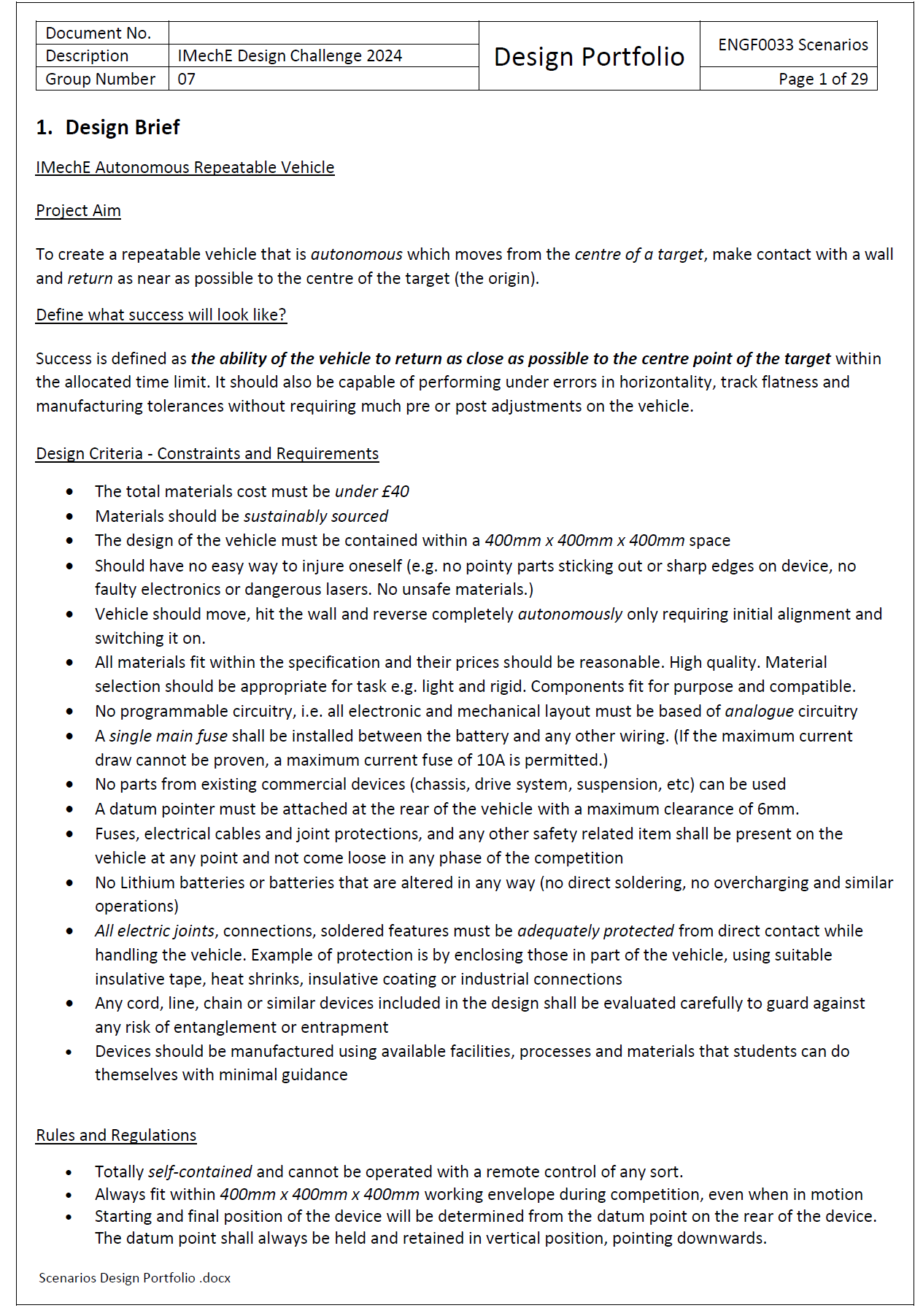
IMechE Repeatable Vehicle Design Challenge

A two-week engineering challenge to design an autonomous mechanical vehicle capable of travelling forward, hitting a wall, and returning to its start point — with no programming or electronics.
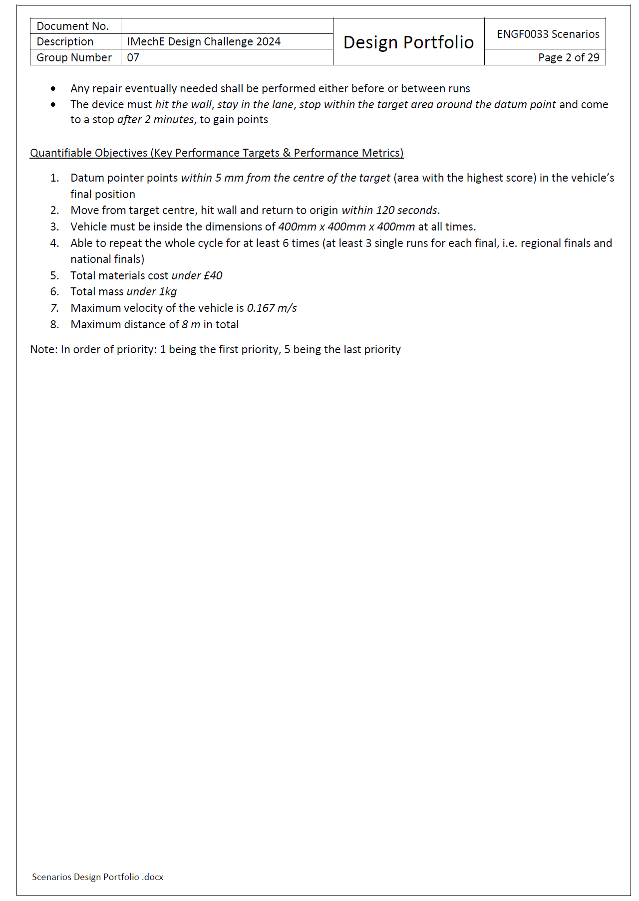
Project Overview
The IMechE Design Challenge tasked us with designing a fully autonomous repeatable vehicle capable of travelling from a defined start point, colliding gently with a wall, and returning precisely to the origin—without any programming, electronics, or remote control.
Working across UCL’s Scenarios Week, we approached this as professional engineers: understanding requirements, analysing constraints, generating concepts, modelling mechanisms, and producing a fully justified virtual prototype ready for manufacture. This project combined teamwork, engineering analysis, CAD modelling, and rapid decision-making under pressure.
Challenge Requirements
Our vehicle needed to meet the following strict criteria:
£40 total material budget
Must fit within 400 × 400 × 400 mm
Entirely mechanical — no electronics or programming
Travel forward → touch a wall → return to start
Datum pointer must finish within 5 mm of the origin
Must complete operation within 120 seconds
Safe, stable, and fully self-contained
Demonstrate repeatability, not just single performance
These constraints shaped every design decision we made.
My Role - Team Lead & Mechanical Designer
As Team Lead and Mechanical Designer, I was responsible for:
Leading the design direction and team coordination
Creating the complete CAD assembly in Fusion 360
Performing gear ratio calculations and mechanical modelling
Designing the drive system, reverse mechanism, and impact system
Producing analytical graphs and simulations
Preparing deliverables and presenting our engineering justification
Creating a Bill of Materials and managing costs.
This role combined leadership, mechanical reasoning, and technical execution.
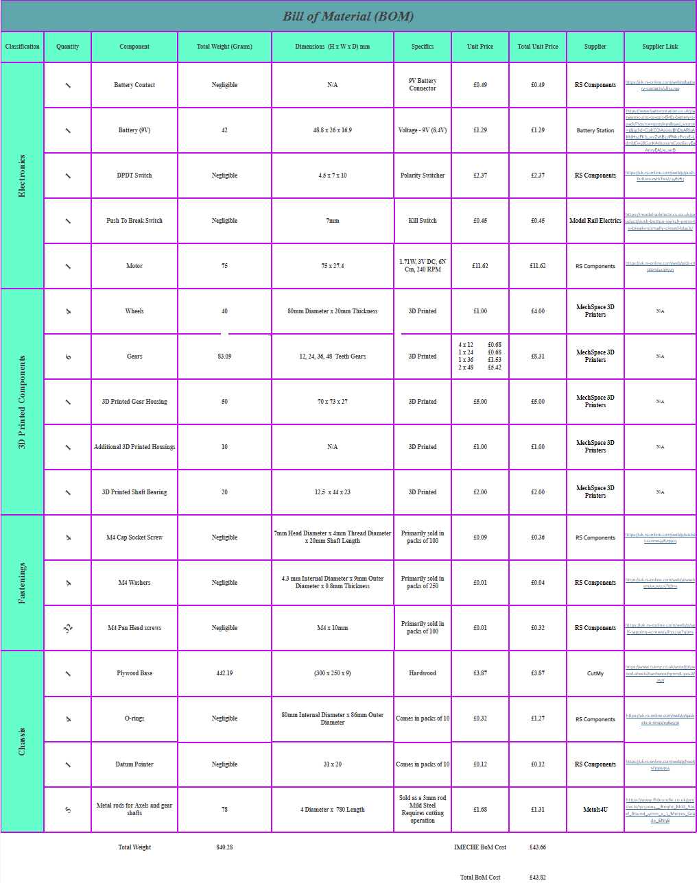
Bill of Materials
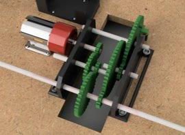
Gear Drive System
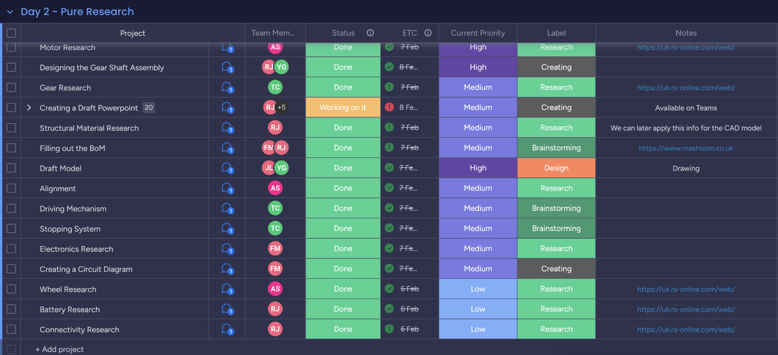
Workflow Management
Phase 1 - Problem Exploration
Interpreting the Brief
Our first task was to translate the specification into a set of engineering challenges. The core difficulty was achieving consistent, repeatable motion using only mechanical components. Factors such as surface friction, wheel slip, alignment, motor variability, and impact behaviour all significantly influence accuracy.
Key Engineering Challenges Identified
Ensuring consistent forward motion without wheel slip
Creating a reliable, fully mechanical reverse trigger
Mechanically measuring distance without electronics
Designing a safe and predictable wall collision system
Controlling the return behaviour to end within 5 mm
Keeping costs and manufacturing complexity low
Understanding these challenges guided our research and concept generation.
Phase 2 — Research & Concept Development
Early Concepts and Exploration
We explored several mechanisms across five subsystems:
Drive System: motor-driven gear train, 4-wheel drive
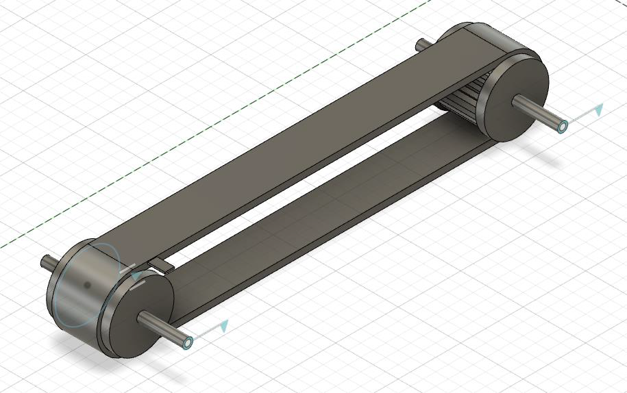
Distance Measurement: slow-tracking gear, belt-based measurement, mechanical counters
Reverse Mechanism: DPDT mechanical switch, spring reset, wall-trigger levers
Alignment: laser pointer with ground marking guides
Impact System: rigid stops vs. spring dampers
Each concept was evaluated against repeatability, safety, manufacturability, and compliance.
Concept Selection
Using a weighted decision matrix, we selected the following configuration:
A DPDT toggle switch to reverse motor polarity upon wall contact
A slow gear (1:16 ratio) for accurate travel measurement
Laser alignment system to improve start-line precision
A front-mounted spring damper to absorb collision forces
A high-traction wheel system to minimise slip
This combination offered the best balance of simplicity, accuracy, and reliability.
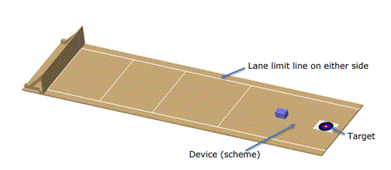
Testing Environment
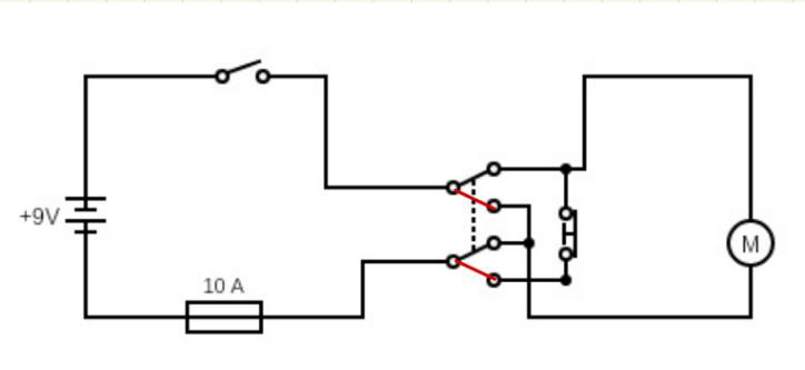
Vehicle Circuit Diagram
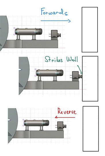
Vehicle Reversing Mechanism
CAD Prototype 1

Slow Gear Kill Mechanism
Phase 3 — Engineering Modelling & Analysis
Kinematic and Dynamic Modelling
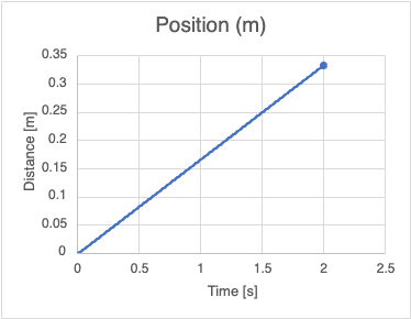
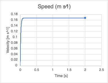
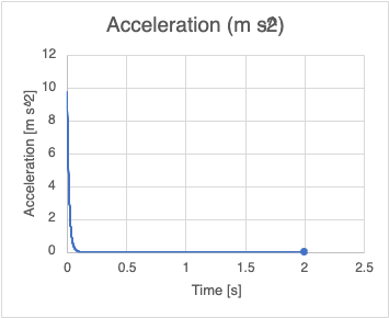
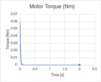
Using mathematical modelling, we evaluated the vehicle’s motion across the full travel path.
Key results from our modelling:
Top speed: 0.167 m/s
Time to reach max speed: 0.15 seconds
Impact deceleration: 0.078 g
Impact force: 0.71 N
Estimated round-trip time: < 60 seconds
Friction requirement: μ ≥ 0.6 for reliable traction
We modelled position, velocity, acceleration, torque, and power to verify the motor and gear ratios were suitable.
Wheel Slip Analysis
Surface friction was identified as a major source of error. To mitigate slip:
O-rings were added to increase wheel traction
The vehicle mass distribution was adjusted to increase normal force
Wheel diameter and material were selected to minimise variability
Collision Behaviour
We validated that a spring constant of approximately 2100 N/m would safely control deceleration without causing rebound or excessive stress on the reverse switch.
These analyses ensured the design was justified using engineering principles.
Phase 4 — CAD Development
Modelling the Vehicle
I developed the complete CAD assembly, starting with individual subsystems before integrating them into a coherent final design. The CAD model included:
Frame and housing
Gear trains for both drive and distance systems
Motor mount
Reverse-trigger housing
Datum pointer
Spring-damper for impact
O-ring wheels
Laser support bracket
Iterative Refinement
Across iterations, improvements included:
Weight reduction through material removal
Improved motor alignment
More robust mounting for the DPDT switch
Redesigned front housing for consistent wall triggering
Greater clearance for gears and shafts
These refinements made the design more robust and manufacturable.
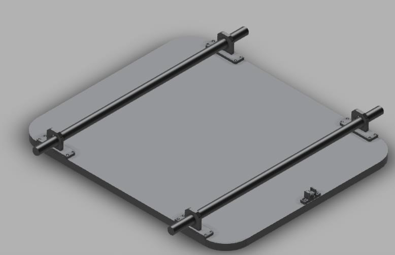
Initial Base Design
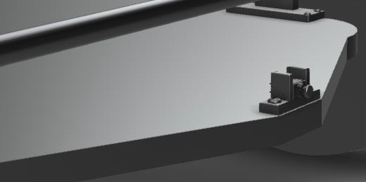
Initial Front Design

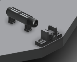
Laser Pointer Attachment + DPDT Switch Holder
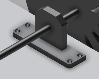
Axle Holder
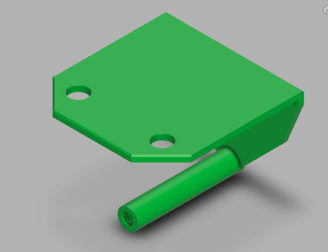
Datum Holder

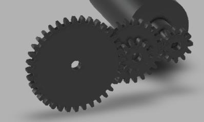
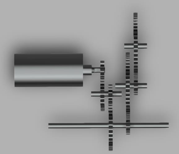
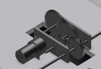
Initial Gear Drive System

Initial CAD Model
Phase 5 — Week 1 → Week 2 Improvements
Between weeks, we implemented significant optimisations:
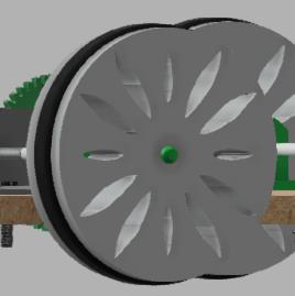
Replaced heavy wheels with lightweight acrylic wheels
Added earlier subsystem-level testing
Reinforced joints and mounting points
Improved gear housing to reduce backlash
Optimised reverse switch contact geometry
Refined alignment system for more repeatable starts
These changes greatly improved expected reliability and repeatability.
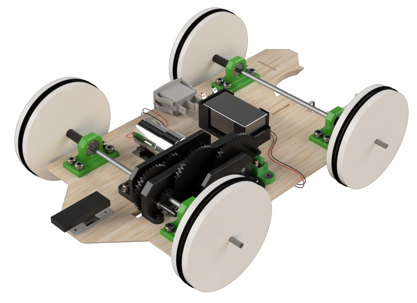
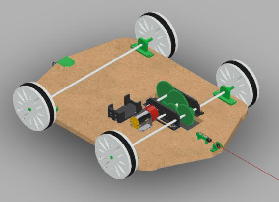
Final CAD Model
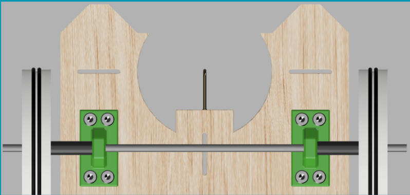
Improved Alignment Design

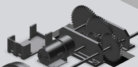
Refined Gear Drive System and Base Design
Subsystem Details
Drive System
Reverse DPDT Mechanism
Distance Measuring System
Alignment System
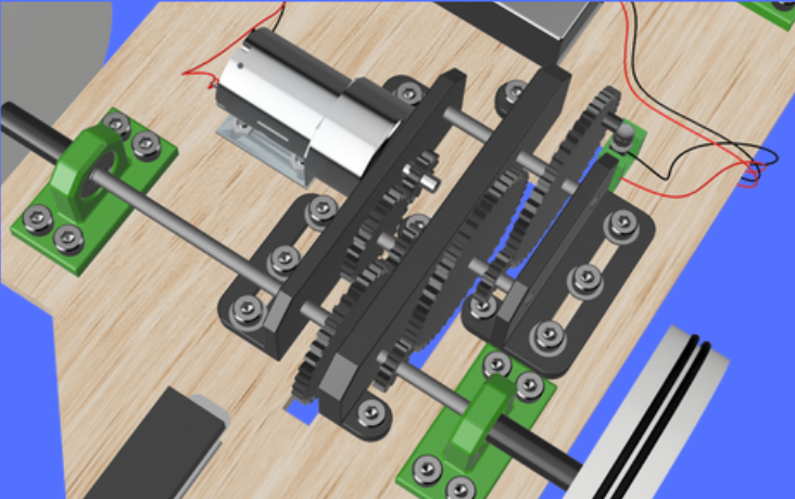
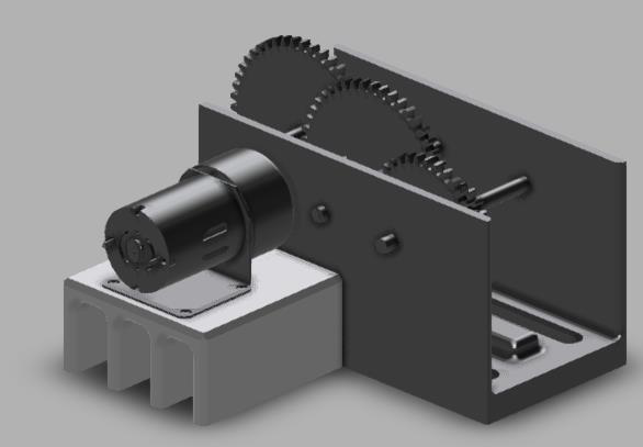
The initial gear housing was too cramped to accommodate the mechanism reliably, so it was redesigned into two sections: the first driving the front axle and the second containing the kill-switch assembly. The image also shows the O-rings added around the acrylic wheels to increase traction and reduce slip.
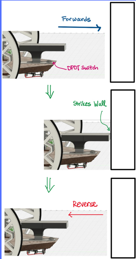
When the vehicle reaches the wall, the custom-designed cap presses against it and triggers the DPDT switch. This action reverses the motor polarity and initiates the return motion.
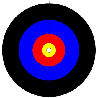
Starting target
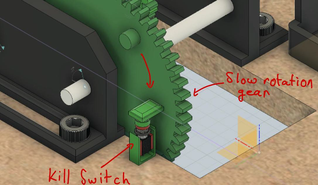
By isolating this switch from the main circuit during forward motion, the cylindrical protrusion can activate it only on the vehicle’s return, cutting power precisely when it reaches the starting position.

The laser pointer system proved insufficient for reliably aligning the vehicle with the target. Instead, the diameter of the red target was cut into the rear of the vehicle’s base, along with three slots that match the dotted guide lines. The datum pointer also aligns with the white circle at the centre, ensuring precise and repeatable positioning.
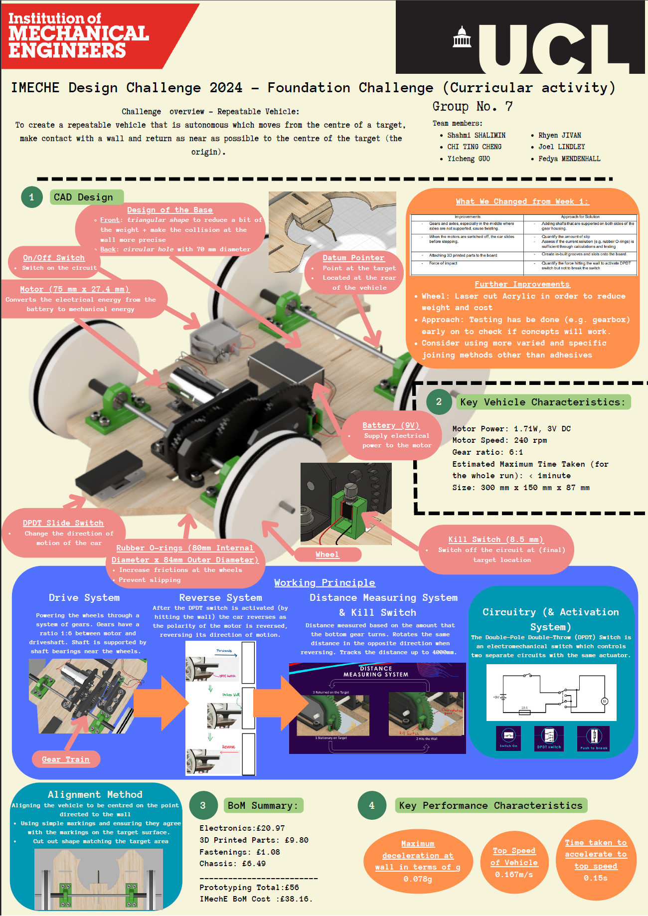
IMECHE Poster
Expected peformance
Our final predicted performance metrics:
Return accuracy: ±3 mm
Total cycle time: < 60 seconds
High repeatability across multiple runs
Stable collision response without rebound
Effective power transmission using 1:6 and 1:16 gear ratios
Fully mechanical autonomy with no electronics
The system met all IMechE requirements with strong safety and reliability.
Final Outcome
The final design is a fully justified mechanical vehicle ready for manufacture and testing. The CAD model accurately represents a buildable prototype, supported by modelling, analysis, and subsystem integration. Each element—from the gear train to the reverse mechanism—was engineered for reliability, simplicity, and repeatability under real conditions.
The project demonstrates strong mechanical engineering principles, teamwork, and effective technical decision-making within tight constraints.
Reflection
This challenge developed my skills in:
Mechanical system design
CAD modelling and design iteration
Gear ratio selection and kinematic analysis
Engineering justification and documentation
Team coordination and time management
It also reinforced the importance of subsystem testing, friction management, and early validation. With more time, I would refine materials, optimise assembly tolerances, and explore additional alignment methods to reduce systematic error even further.